 |
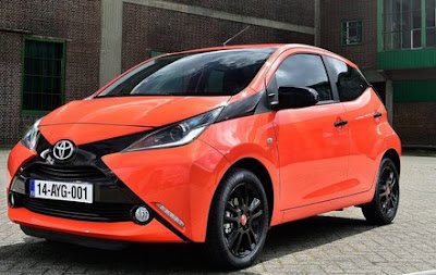
| 2015 Tyota Aygo |
Checking and replacing fuses
If any of the electrical components do not operate, a fuse may have blown. If this happens, check and replace the fuses as necessary.
1 .Vehicles without a smart entry & start system:
Turn the engine switch to the “LOCK” position.
Vehicles with a smart entry & start system:
Turn the engine switch off.
2. After a system failure, see “Fuse layout and amperage ratings” for details about which fuse to check.
3. Open the fuse box cover.
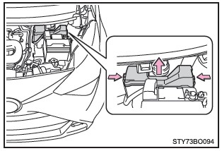 |
Engine compartment - Push the tabs in and lift the cover off. |
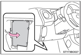 |
| Driver’s side instrument panel - Remove the cover. |
4. Remove the fuse with the pullout tool (Fuse Puller).
Only type A fuse can be removed using the pullout tool.
Only type A fuse can be removed using the pullout tool.
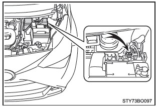 |
| Fuse Puller Location |
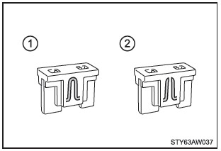
5. Check if the fuse is blown.
(1) Normal fuse
(2) Blown fuse
Type A, B and C: Replace the blown fuse with a new fuse of an appropriate amperage rating.
Type D: Contact any authorized Toyota retailer or Toyota authorized repairer, or any reliable repairer.
(1) Normal fuse
(2) Blown fuse
Type A, B and C: Replace the blown fuse with a new fuse of an appropriate amperage rating.
Type D: Contact any authorized Toyota retailer or Toyota authorized repairer, or any reliable repairer.
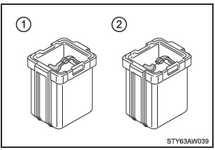 |
| Type B Fuse |
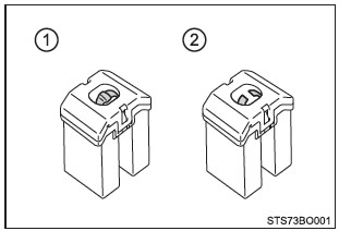 |
| Type C Fuse |
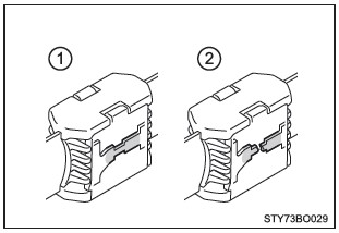 |
| Type D Fuse |
Fuse layout and amperage ratings
Engine compartment
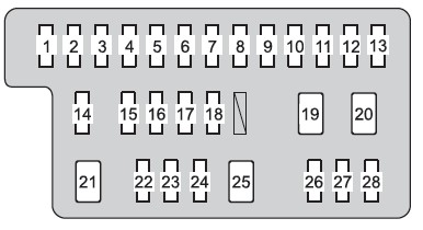
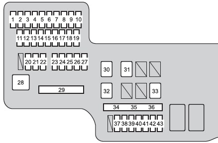 |
| Engine Compartment Fuse Panel Diagram |
# ... Fuse .... Ampere .... Circuit
1 H-LP RH-LO 10 Right-hand headlight (low beam)
2 H-LP LH-LO 10 Left-hand headlight (low beam), manual headlight leveling dial
3 H-LP RH-HI 7.5 Right-hand headlight (high beam)
4 H-LP LH-HI 7.5 Left-hand headlight (high beam), gauges and meters
5 EFI NO.3*1 15 Multiport fuel injection system/sequential multiport fuel injection system
6 EFI NO.4*1 7.5 Multiport fuel injection system/sequential multiport fuel injection system
7 EFI NO.5*1 15 Multiport fuel injection system/sequential multiport fuel injection system
8 RDI NO.2*1 7.5 Electric cooling fan
9 A/C COMP 7.5 Air conditioning system
10 IG2 NO.3*2 7.5 Multiport fuel injection system/sequential multiport fuel injection system, stop lights, high mounted stoplight
11 DOME 5 Interior light, luggage compartment light
12 HAZ 10 Turn signal lights, emergency flashers, gauges and meters
13 HORN 10 Horn
14 D/C CUT 30 ECU-B NO.1, ECU-B NO.2, ECU-B NO.3
15 ECU-B NO.4*2 7.5 Multi-mode manual transmission
16 AM2 NO.2 7.5 Multiport fuel injection system/sequential multiport fuel injection system
17 AM2 NO.3 7.5 Smart entry & start system
18 ICS*2 7.5 Charging system
19 EFI-MAIN*1 25 EFI NO.3, EFI NO.4, EFI NO.5, RDI NO.2
20 ST 30 Starting system
21 STRG LOCK 7.5 Steering lock system
22 H-LP-MAIN 25 H-LP RH-LO, H-LP LH-LO, H-LP RH-HI, H-LP LH-HI
23 WIPER-S*2 7.5 Multiport fuel injection system/sequential multiport fuel injection system
24 STA 7.5 Multiport fuel injection system/sequential multiport fuel injection system, starting
system, multi-mode manual transmission, Stop & Start system
25 ECU-B NO.3 15 Audio system, smart entry & start system
26 ECU-B NO.1 7.5 Gauges and meters
27 ECU-B NO.2 7.5 Vehicle stability control system
28 J/B 60 Instrument fuse box
29 ALT *2 125 DEF, S/HTR F/R, S/HTR F/L, CANVAS TOP, ABS NO.1, ABS NO.2, RDI NO.1,
FOG FR, DRL (Daytime running lights)
30
AMT*3 50 Multi-mode manual transmission
BBC*4 40 Stop & Start system
31 EPS 50 Electric power steering system
32 RDI NO.1 50*1 , 30*5 , 40*5 , Electric cooling fan (Radiator Fan)
33 ABS NO.1 50 Anti-lock brake system (ABS), vehicle stability control system
34 SPARE 10 Spare fuse
35 SPARE 20 Spare fuse
36 SPARE 30 Spare fuse
37 DEF 20 Rear window defogger, outside rear view mirror defoggers
38 ABS NO.2 30 Anti-lock brake system (ABS), vehicle stability control system
39 FOG FR 7.5 Front fog lights, gauges and meters
40 DRL 7.5 Daytime running lights
41 S/HTR F/R 15 Seat heaters (right side)
42 CANVAS TOP 20 Canvas top
43 S/HTR F/L 15 Seat heaters (left side)
*1: HM01 engine
*2: 1KR engine
*3: Vehicles with a multi-mode manual transmission
*4: Vehicles with a Stop & Start system
*5: Replace the fuse with one of the same ampere rating as the original
Driver’s side instrument panel
 |
| Driver's Side Fuse Panel Diagram |
# ... Fuse .... Ampere .... Circuit
1 IG1 NO.2 5 Back-up light, multiport fuel injection system/ sequential multiport fuel injection
system, audio system, vehicle stability control system
2 WASHER 15 Windshield washer, rear window washer
3 ECU-IG NO.1 5 Main body ECU, gauges and meters, air conditioning system, rear window defogger, outside rear view mirror defoggers, seat heaters, canvas top, audio system, PCS system
4 ECU-IG NO.2 5 Electric power steering system, Stop & Start system
5 WIPER RR 15 Rear window wiper
6 IG1 NO.1 5 Electric cooling fan, anti-lock brake system, vehicle stability control system
7 WIPER 25 Windshield wiper
8 MIR HTR 10 Outside rear view mirror defoggers
9 P/OUTLET 15 Power outlet
10 ECU-ACC 7.5 Outside rear view mirrors, audio system, Stop & Start system, gauges and meters
11 IG2 NO.2 5 Steering lock system, multiport fuel injection system/sequential multiport fuel
injection system, multi-mode manual transmission
12 A/BAG 7.5 SRS airbag system
13 METER 5 Gauges and meters, Stop & Start system
14 IG2 NO.1 15 *1 ; 7.5 *2 Multiport fuel injection system/sequential multiport fuel injection system, stop lights
15 EFI NO.1 7.5 *1 , 10 *2 Multiport fuel injection system/sequential multiport fuel injection system, Stop & Start system
16 OBD 7.5 On-board diagnosis system
17 STOP 10 Stop lights, high mounted stoplight, multiport fuel injection system/sequential multiport fuel injection system, anti-lock brake system (ABS), vehicle stability control system, multi-mode manual transmission, smart entry & start system
18 TAIL 10 Position lights, license plate lights, rear fog light, front fog lights, tail lights, switch
illumination, multiport fuel injection system/ sequential multiport fuel injection system, gauges and meters, audio system
19 HTR 40 Air conditioning system
20 AM1 40 HTR, OBD, A/C, TAIL, FOG RR, STOP, P/W, DOOR F/L, DOOR F/R
21 AM2 NO.1 30 EFI NO.2, EFI-MAIN, D/L
22 EFI NO.2 *1 7.5 Multiport fuel injection system/sequential multiport fuel injection system
23 EFI-MAIN*1 20 EFI NO.1, multiport fuel injection system/ sequential multiport fuel injection system, fuel pump
24 D/L 25 Main body ECU, door lock system
25 P/W 30 Power windows
26 DOOR F/R*3 , DOOR F/L*4 25 Power windows
27 A/C 10 Air conditioning system
28 FOG RR 5 Rear fog light
*1: 1KR engine
*2: HM01 engine
*3: Left-hand drive vehicles
*4: Right-hand drive vehicles
After a fuse is replaced
●If the lights do not turn on even after the fuse has been replaced, a bulb may need replacement.
●If the replaced fuse blows again, have the vehicle inspected by any authorized Toyota retailer or Toyota authorized repairer, or any reliable repairer.
■If there is an overload in a circuit
The fuses are designed to blow, protecting the wiring harness from damage.
WARNING
■To prevent system breakdowns and vehicle fire
Observe the following precautions.
Failure to do so may cause damage to the vehicle, and possibly a fire or injury.
●Never use a fuse of a higher amperage rating than that indicated, or use any other object in place of a fuse.
●Always use a genuine Toyota fuse or equivalent.
Never replace a fuse with a wire, even as a temporary fix.
●Do not modify the fuses or fuse boxes.
NOTICE - Before replacing fuses
Have the cause of electrical overload determined and repaired by any authorized Toyota retailer or Toyota authorized repairer, or any reliable repairer as soon as possible.

No comments:
Post a Comment