Fuses and Relays
WARNING
-
When replacing a blown fuse, always use an appropriate replacement fuse
with the same amp rating as the original fuse. Never replace a fuse
with another fuse of higher amp rating. Never replace a blown fuse with
metal wires or any other material. Do not place a fuse inside a circuit
breaker cavity or vice versa. Failure to use proper fuses may result in
serious personal injury, fire and/or property damage.
- Before replacing a fuse, make sure that the ignition is off and that all the other services are switched off and/or disengaged.
- If the replaced fuse blows again, contact an authorized dealer.
- If a general protection fuse for safety systems (air bag system, braking system), power unit systems (engine system, transmission system) or steering system blows, contact an authorized dealer.
CAUTION
If it is necessary to wash the engine compartment, take care not to directly hit the fuse box, and the windshield wiper motors with water.
The fuses protect electrical systems against excessive current.
When a device does not work, you must check the fuse element inside the blade fuse for a break/melt.
Also, please be aware that when using power outlets for extended periods of time with the engine off may result in vehicle battery discharge.
When a device does not work, you must check the fuse element inside the blade fuse for a break/melt.
Also, please be aware that when using power outlets for extended periods of time with the engine off may result in vehicle battery discharge.
1 — Fuse Element
2 — Blade Fuse with a good/functional fuse element
3 — Blade fuse with a bad/not functional fuse element (blown fuse)
2 — Blade Fuse with a good/functional fuse element
3 — Blade fuse with a bad/not functional fuse element (blown fuse)
Underhood Fuses
The Front Power Distribution Center is located on the driver’s side of the engine compartment.
To access the fuses, remove the cover.
The ID number of the electrical component corresponding to each fuse can be found on the
back of the cover.
Cavity ... Maxi Fuse ... Mini Fuse .... Description
F01 40 Amp Orange – Electronic Stability Control (ESC) Pump
F02 20 Amp Yellow (3.6 Gasoline Engine) – Starter Relay 3.6L (3.6 Gasoline Engine)
back of the cover.
Cavity ... Maxi Fuse ... Mini Fuse .... Description
F01 40 Amp Orange – Electronic Stability Control (ESC) Pump
F02 20 Amp Yellow (3.6 Gasoline Engine) – Starter Relay 3.6L (3.6 Gasoline Engine)
2018 Model - F03 30 Amp Green UREA (3.0 Diesel Engine)
2018 Model - F02 50 Amp Red (3.0 Diesel Engine) – Glow Plug Unit (3.0 Diesel Engine)
F04 50 Amp Red (3.6 Gasoline Engine) – Secondary Power Distribution Center (PDC) (Trans Power Relay, Vacuum Pump, KL30 for the Shifter Transmission Module [STM]) (3.6 Gasoline Engine)
F06
2018 Model - F02 50 Amp Red (3.0 Diesel Engine) – Glow Plug Unit (3.0 Diesel Engine)
F04 50 Amp Red (3.6 Gasoline Engine) – Secondary Power Distribution Center (PDC) (Trans Power Relay, Vacuum Pump, KL30 for the Shifter Transmission Module [STM]) (3.6 Gasoline Engine)
F06
40 Amp Orange (non A/C)
60 Amp Blue (A/C)
– Engine Cooling Fan - 2nd Speed
60 Amp Blue (A/C)
– Engine Cooling Fan - 2nd Speed
F07
50 Amp Red (non A/C)
60 Amp Blue (A/C)
– Engine Cooling Fan - 1st Speed
F08 40 Amp Orange – Passenger Compartment Blower
F09 – 15 Amp Blue Rear Power Outlet
F10 – 15 Amp Blue Horn
F14 – 20 Amp Yellow Power Outlet (Cigarette Lighter)
F15 – 7.5 Amp Brown USB Charger
F16 – 7.5 Amp Brown KL15 Shifter Transmission Module (STM) (3.6), KL15 Starter Relay Coil (3.6 Gasoline Engine)
F17 – 20 Amp Yellow Engine Control Module (ECM), Injectors (3.6 Gasoline Engine)
F18 – 7.5 Amp Brown KL30 Engine Control Module (ECM), KL30 Main Relay Coil (3.6 Gasoline Engine)
F19 – 7.5 Amp Brown A/C Compressor — If Equipped
F20 – 30 Amp Green Windshield Wiper
F21 – 15 Amp Blue Fuel Pump
F22 – 20 Amp Yellow Engine Control Module (ECM), Ignition Coils (3.6 Gasoline Engine)
F23 – 20 Amp Yellow Electronic Stability Control (ESC) Valves
F24 – 7.5 Amp Brown KL15 Vacuum Pump Relay Coil (3.6 Gasoline Engine) — If Equipped
F30 – 15 Amp Blue Heated Mirrors
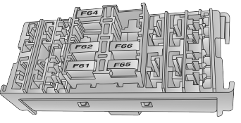
Front PDC Additional Fuses
The additional fuse box is located inside the front PDC Box.
 |
| Front Power Distribution Center Additional Fuses |
Cavity ... Mini Fuse .... Description
F61 20 Amp Yellow Vacuum Pump (3.6 Gasoline Engine) — If Equipped
F62 30 Amp Green Transmission Power RELE (3.6 Gasoline Engine)
2018 Model - F64 7.5 Amp Brown Urea Pump (3.0 Diesel Engine) — If Equipped
2018 Model - F65 20 Amp Yellow UREA NOX SNS 1-2 + PM SNS (3.0 Diesel Engine) — If Equipped
F66 5 Amp Beige Shifter Transmission Module (STM) (3.6 Gasoline Engine)
2018 Model - F65 20 Amp Yellow UREA NOX SNS 1-2 + PM SNS (3.0 Diesel Engine) — If Equipped
F66 5 Amp Beige Shifter Transmission Module (STM) (3.6 Gasoline Engine)
Interior Fuses
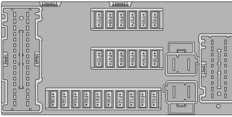
The interior fuse panel is part of the Body Control Module (BCM) and is located on the driver's side under the instrument panel.
 |
| Interior Fuse Panel |
Cavity ... Mini Fuse ... Description
F12 10 Amp Red Right Low Beam
F13 10 Amp Red Left Low Beam
F31 5 Amp Beige INT/A
F32 10 Amp Red SBMT
F31 5 Amp Beige INT/A
F34 7.5 Amp Brown Clearance Lights
F36 15 Amp Blue +30 (ACM – TPCU – RRM – DLC)
F37 5 Amp Beige INT (BRAKE NO – IPC)
F38 15 Amp Blue Central Locking
F42 5 Amp Beige INT (BSM – SAS – BRAKE NC) / DASM
F43 20 Amp Yellow Bi-Directional Washer Pump
F47 20 Amp Yellow Driver Power Window
F48 20 Amp Yellow Passenger Power Window
F49 5 Amp Beige INT (PAM – CCS – RRM – ECM)
F50 7.5 Amp Brown INT (ORC)
F51 5 Amp Beige INT (REAR CAMERA-AUX) / HALF-DRVM-BSD
F53 5 Amp Beige +30 (IPC) + FTM
F92 7.5 Amp Brown Left Fog Lamp
F93 7.5 Amp Brown Right Fog Lamp
Right Central Pillar Fuses
The right central pillar fuse panel is located on the interior side at the base of the passenger
side B-pillar.
 |
| Right Central Pillar Fuse Panel Location |
 |
| Right Central Pillar Fuse Panel Diagram |
Cavity ... Mini Fuse ... Description
F81 7.5 Amp Brown Seat Heater
F83 20 Amp Yellow Rear Left Windows Heater
F84 20 Amp Yellow Rear Right Windows Heater
F86 20 Amp Yellow Auxiliary Switch (From Battery) — If Equipped
F87 20 Amp Yellow Auxiliary Switch (From Ignition) — If Equipped


No comments:
Post a Comment