Fuses and Relays
A vehicle’s electrical system is protected from electrical overload damage by fuses.
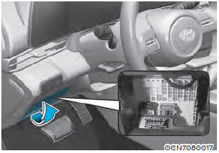
This vehicle has 2 (or 3) fuse panels, one located in the driver’s side panel bolster, the other in the engine compartment near the battery.
If any of your vehicle’s lights, accessories, or controls do not work, check the appropriate circuit fuse. If a fuse has blown, the element inside the fuse will be melted or broken.
If the electrical system does not work, first check the driver’s side fuse panel.
Before replacing a blown fuse, turn the engine and all switches off, and then disconnect the negative battery cable.
Always replace a blown fuse with one of the same rating.
If the replacement fuse blows, this indicates an electrical problem.
Avoid using the system involved and immediately consult an authorized HYUNDAI dealer.
WARNING
NEVER replace a fuse with anything but another fuse of the same rating.
• A higher capacity fuse could cause damage and possibly cause a fire.
• Do not install a wire or aluminum foil instead of the proper fuse - even as a temporary repair. It may cause extensive wiring damage and possibly a fire.
NOTICE
Do not use a screwdriver or any other metal object to remove fuses because it may cause a short circuit and damage the system.
Instrument Panel Fuse Replacement
1. Turn the vehicle off.
2. Turn all other switches OFF.
3. Open the fuse panel cover.
4. Refer to the label on the inside of the fuse panel cover to locate the suspected fuse location.
2. Turn all other switches OFF.
3. Open the fuse panel cover.
4. Refer to the label on the inside of the fuse panel cover to locate the suspected fuse location.
5. Pull the suspected fuse straight out. Use the removal tool provided in the engine compartment fuse panel.
6. Check the removed fuse; replace it if it is blown. Spare fuses are provided in the engine compartment fuse panel.
7. Push in a new fuse of the same rating, and make sure it fits tightly in the clips. If it fits loosely, consult an authorized HYUNDAI dealer.
In an emergency, if you do not have a spare fuse, use a fuse of the same rating from a circuit you may not need for operating the vehicle.
If the other electrical components do not work and the fuses are undamaged, check the fuse panel in the engine compartment. If a fuse is blown, it must be replaced with the same rating.
If the headlamp, turn signal lamp, tail lamp, interior lamp doesn’t work and the fuses are undamaged, consult an authorized HYUNDAI dealer.
Engine Compartment Panel Fuse Replacement
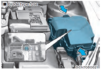 |
| „„Blade type fuse |
1. Turn the engine off.
2. Turn all other switches OFF.
3. Remove the fuse panel cover by pressing the tap and pulling up.
4. Check the removed fuse; replace it if it is blown. To remove or insert the fuse, use the fuse puller in the engine compartment fuse panel.
5. Push in a new fuse of the same rating, and make sure it fits tightly in the clips. If it fits loosely, consult an authorized HYUNDAI dealer.
CAUTION
After checking the fuse box in the engine compartment securely close the fuse box cover inside the engine compartment, until it clicks.
If the fuse box is not closed properly, water may leak in side, possibly causing a malfunction with the electrical system.
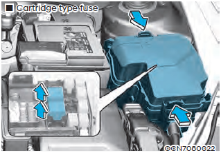
Multi fuse (Main fuse)
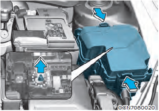 |
| Multi fuse (Main fuse) |
If the multi fuse is blown, it must be removed as follows:
1. Turn off the engine.
2. Disconnect the negative battery cable.
3. Remove the fuse panel cover by pressing the tab and pulling it up.
4. Remove the nuts shown in the picture above.
5. Replace the fuse with a new one of the same rating.
6. Reinstall in the reverse order of removal.
Information
If the multi fuse is blown, consult an authorized HYUNDAI dealer.
Fuse/Relay Panel Description
Instrument panel fuse panel
 |
| Instrument panel fuse panel Cover |
Inside the fuse/relay box cover, you can find the fuse/relay label describing fuse/ relay names and ratings.
Information
Not all fuse panel descriptions in this manual may be applicable to your vehicle; the information is accurate at the time of printing. When you inspect the fuse box on your vehicle, refer to the fuse box label.
 |
| Instrument fuse panel Diagram |
Fuse Name .. Fuse Rating .. Circuit Protected
MEMORY1 10A Instrument Cluster, A/C Controller, A/C Control Module, DRV/PASS Folding Outside Mirror
AIR BAG2 10A SRS Control Module
MODULE4 10A
Lane Keeping Assist Unit (LINE), Crash Pad Switch, IBU,
Parking Collision Avoidance Assist Unit, A/T Shift Lever
Indicator, Front Console Switch
MODULE7 7.5A Parking Collision Avoidance Assist Unit, IAU, Rear Seat
Warmer Control Module
START 7.5A Burglar Alarm Relay, Transaxle Range Switch, PCM/
ECM IBU, E/R Junction Block (Start Relay)
CLUSTER 7.5A Instrument Cluster
IBU2 7.5A IBU
A/C1 7.5A E/R Junction Block (PTC Heater Relay, Blower Relay),
A/C Control Module, A/C Controller
TRUNK 10A Trunk Lid Latch, Trunk lid Switch
S/HEATER FRT 20A Front Seat Warmer Control Module
P/WINDOW LH 25A Power Window Main Switch
MULTIMEDIA 15A Audio, A/V & Navigation Head Unit, DC-DC Converter
FCA 10A Forward Collision Avoidance Assist Unit
MDPS 7.5A MDPS Unit
MODULE6 7.5A IBU
S/HEATER RR 20A Rear Seat Warmer Control Module
SAFETY P/
WINDOW DRV 25A Driver Safety Power Window Module
P/WINDOW RH 25A Power Window Main Switch, Passenger Power Window Switch
BRAKE SWITCH 10A Stop Lamp Switch, IBU
IBU1 15A IBU
MODULE2 10A
E/R Junction Block (Power Outlet Relay), AMP, IBU,
IAU, Audio, Power Outside Mirror Switch, Parking
Collision Avoidance Assist Unit, DC-DC Converter, A/V &
Navigation Head Unit
AIR BAG1 15A SRS Control Module, Passenger Occupant Detection Sensor
MODULE5 10A A/T Shift Lever Indicator, Front Wireless Charger, A/C Controller, Electro Chromic Mirror, A/C Control Module, Audio, A/V & Navigation Head Unit, AMP, DC-DC
Converter, Data Link Connector, Rear Seat Warmer Control Module, Front Seat Warmer Control Module
AMP 25A AMP, DC-DC Converter
HEATED MIRROR 10A DRV/PAS Outside Mirror Heated, A/C Control Module,
A/C Controller
DOOR LOCK 20A DRV/PAS DOOR ACTUATOR
IAU 10A BLE Unit, IAU, Driver/Passenger Door NFC Module
MODULE3 7.5A Stop Lamp Switch, IAU
A/BAG IND 7.5A Instrument Cluster, Overhead Console Lamp
WASHER 15A Multifunction Switch
P/SEAT PASS 30A Passenger Seat Manual Switch
P/SEAT DRV 30A Driver Seat Manual Switch
WIPER 10A PCM/ECM, IBU
MODULE1 10A Driver/Passenger Smart Key Outside Handle, Crash Pad Switch, Sport Mode Switch, Data Link Connector, Hazard Switch, Key Solenoid
SUNROOF 20A Sunroof Motor, Data Link Connector
USB CHARGER 15A Front USB Charger
IG1 25A PCB Block (Fuse - ABS3, ECU5, EOP2, TCU2)
Engine compartment fuse panel
Inside the fuse/relay box cover, you can find the fuse/relay label describing fuse/ relay names and ratings.
Information
Not all fuse panel descriptions in this manual may be applicable to your vehicle; the information is accurate at the time of printing. When you inspect the fuse panel in your vehicle, refer to the fuse panel label.
 |
| Engine compartment fuse panel Diagram |
Type .. Fuse Name .. Fuse Rating .. Circuit Protected
MULTI FUSE-3
ALT
150A [G4NS-W/O AMS2] Alternator, (Fuse - ABS1, ABS2, EOP1, POWER OUTLET1)
180A [G4FP/G4NS-WIth AMS2] Alternator, (Fuse - ABS1, ABS2, EOP1, POWER OUTLET1)
MDPS1 80A MDPS Unit
180A [G4FP/G4NS-WIth AMS2] Alternator, (Fuse - ABS1, ABS2, EOP1, POWER OUTLET1)
MDPS1 80A MDPS Unit
MULTI FUSE-1
B+5 60A PCB Block (Engine Control Relay, Fuse -
ECU3, ECU4, HORN, WIPER, A/C)
B+1 60A ICU Junction Block (IPS2/IPS5/IPS6/IPS7/ IPS14)
B+2 60A ICU Junction Block (IPS1/IPS4/IPS8/IPS9/ IPS10)
B+3 50A ICU Junction Block (Fuse - TRUNK, AMP, SAFETY P/WINDOW DRV, P/SEAT DRV, P/ SEAT PASS, S/HEATER FRT, S/HEATER RR, Long Term Load Latch Relay)
EPB 60A ESC Control Module
PTC HEATER 50A PTC HEATER
BLOWER 40A BLOWER, DATC
IG1 40A E/R Junction Block (PDM (IG1/ACC) Relay), Ignition Switch
IG2 40A E/R Junction Block (PDM (IG2) Relay, Start Relay), Ignition Switch
Type .. Fuse Name .. Fuse Rating .. Circuit Protected
FUSE
POWER OUTLET2 20A Front Power Outlet
POWER OUTLET3 20A Not Used
COOLING FAN1 40A Cooling Fan
DCT1 40A Not Used
DCT2 40A Not Used
REAR HEATED 40A Rear glass heated
B+4 40A ICU Junction Block (Fuse - AIR BAG2, IBU1, BRAKE SWITCH, DOOR LOCK, IAU,
MODULE1, SUNROOF,Power Window Relay)
AMS 10A Battery Sensor
TCU1 10A [DCT] TCM, [M/T] Ignition Lock Switch
FUEL PUMP 20A Fuel Pump Control Module (T-GDI), Fuel Pump Motor (NU MPI AKS)
CVVD 40A Not Used
ABS1 40A ABS Control Module, ESC Control Module, Multipurpose Check Connector
ABS2 30A ABS Control Module, ESC Control Module, Multipurpose Check Connector
EOP1 30A Electronic Oil Pump
POWER OUTLET1 40A P/OUTLET FRT
WIPER 25A Wiper Motor
ECU4 15A PCM/ECM
A/C 10A [G4FM] A/C Compressor
HORN 15A Horn
IGN COIL 20A Ignition Coil #1~#4
ECU3 15A PCM/ECM
SENSOR3 10A E/R Junction Block (Fuel Pump Relay)
ECU2 10A Not Used
SENSOR2 10A [G4NS] Variable Intake Solenoid Valve, Oil Pump Solenoid Valve, Oil Control Valve #1/#2, Canister Close Valve, Purge Control Solenoid Valve, PCB Block (A/C Relay), E/R Junction Block (Cooling Fan1/2 Relay)
ECU5 10A ECM/PCM, [MT] Ignition Lock Switch
SENSOR1 15A Oxygen Sensor (UP/DOWN)
ABS3 10A ABS Control Module, ESC Control Module
INJECTOR 15A [G4FM/G4FG/G4NA] Injector #1~#4
ECU1 20A PCM/ECM
TCU2 15A Transaxle Range Switch
ECU1 20A PCM/ECM
TCU2 15A Transaxle Range Switch



No comments:
Post a Comment