Fuses and Circuit Breakers
The wiring circuits in the vehicle are protected from short circuits by fuses. This greatly reduces the chance of damage caused by electrical problems.
Danger
Fuses and circuit breakers are marked with their ampere rating. Do not exceed the specified amperage rating when replacing fuses and circuit breakers. Use of an oversized fuse or circuit breaker can result in a vehicle fire. You and others could be seriously injured or killed.
Warning
Installation or use of fuses that do not meet GM’s original fuse specifications is dangerous. The fuses could fail, and result in a fire. You or others could be injured or killed, and the vehicle could be damaged.
To check a fuse, look at the silver-colored band inside the fuse. If the band is broken for melted, replace the fuse. Be sure to replace a bad fuse with a new one of the identical size and rating.
Fuses of the same amperage can be temporarily borrowed from another fuse location, if a fuse goes out. Replace the fuse fas soon as possible.
Engine Compartment Fuse Block
If the vehicle has a diesel engine, see the Duramax diesel supplement.
The engine compartment fuse block is in the engine compartment, on the driver side of the vehicle. Lift the cover to access the fuse block.
The engine compartment fuse block is in the engine compartment, on the driver side of the vehicle. Lift the cover to access the fuse block.
Caution
Spilling liquid on any electrical component on the vehicle may damage it. Always keep the covers on any electrical component.
A fuse puller is available inside this fuse block.
 |
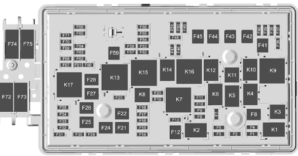
| Engine Compartment Fuse Panel Diagram |
The vehicle may not be equipped with all of the fuses, relays, and features shown.
Fuses .. Usage
F1 Traction control module power
F2 Engine control module power
F3 Air conditioning clutch
F4 –
F5 Engine control module ignition/Integrated chassis control module/ Fuel pump power
module
F6 Wipers
F7 Cargo lamp/Bed lighting
F8 Fuel injectors – even
F9 Fuel injectors – odd
F10 Engine control module 1
F11 Oxygen/Mass air flow/ Humidity/Induction air temperature/Throttle inlet pressure sensors
F12 Starter
F13 Traction control module
F14 –
F15 –
F16 –
F17 Front axle actuator
F18 –
F19 Aeroshutters
F20 –
F21 Front blower
F22 Antilock brake system valves
F23 –
F24 Trailer
F25 Transfer case electronic control
F26 Antilock brake system pump
F27 Trailer brake control module/Trailer wiring provisions
F28 Rear window defogger
F29 –
F30 Driver heated seat
F31 –
F32 Passenger heated seat
F33 Right headlamp low beam/Front right park lamp/Right front side marker/Right rear side
marker
F34 Fuel pump power module
F35 Integrated chassis control module
F36 Center high-mounted stoplamp
F37 Right high-beam headlamp
F38 Left high-beam headlamp
F39 –
F40 –
F41 –
F42 –
F43 Not used
F44 –
F45 Vaccuum pump
F46 Engine control module 2
F47 Mid park phase lock/ Active fuel management/Engine oil and canister purge solenoid(s)/Oxygen sensor
F48 Fog lamps
F49 –
F50 Trailer parking lamps
F51 Horn
F52 –
F53 –
F54 –
F55 –
F56 Washer pump
F57 –
F58 –
Fuses Usage
F59 –
F60 Mirrors defogger
F61 –
F62 Canister vent solenoid
F63 –
F64 Trailer reverse lamp
F65 Left trailer stoplamp/ Turn signal lamps
F66 Right trailer stoplamp/ Turn signal lamps
F67 Electric power steering
F68 –
F69 Battery regulated voltage control
F70 –
F71 –
F72 –
F73 –
F74 Generator
F75 –
Relays .. Usage
K1 Air conditioning clutch
K2 Starter
K3 –
K4 Wipers speed
K5 Wipers control
K6 Cargo lamp/Bed lighting
K7 Powertrain
K8 –
K9 –
K10 –
K11 Center high-mounted stoplamp
K12 –
K13 Vacuum pump
K14 Trailer parking lamps
K15 Run/Crank
K16 –
K17 Rear window defogger
Instrument Panel Fuse Block
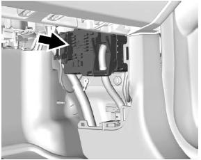
The instrument panel fuse block is behind the passenger side cowl side trim panel. Remove the plastic nut at the front of the cover, then pull the cover away from the trim panel to access the fuse block.
 |
| Instrument Fuse Panel Diagram |
The vehicle may not be equipped with all of the fuses, relays, and features shown.
Fuses .. Usage
F1 Run/Crank relay control/ Horn switch/Dome lamps
F1 Run/Crank relay control/ Horn switch/Dome lamps
F2 –
F3 –
F4 Steering wheel controls
F5 Left headlamp low beam/ Front left park lamp/Left front side marker/Left rear side marker
F6 –
F7 –
F8 Mirror window module
F9 Instrument panel
F10 –
F11 Door latches
F12 –
F13 OnStar/HVAC
F14 Radio/Infotainment
F15 RAP accessory relay control/Shifter control/ Shifter solenoid/Wiper , relay control/Washer pump , relay control/Rear defog , relay control
F16 Communication gateway module
F17 Left rear side marker/Right front turn lamp/Left rear stop lamp/Left front turn lamp/Right rear stop lamp
F18 Airbag/Sensing and diagnostic module/ Automatic occupant sensing module
F19 –
F20 Amplifier
F21 –
F22 –
F23 Data link connector/USB front
F24 HVAC ignition/Auxiliary heater
F25 Driver door latch
F26 –
F27 –
F28 Instrument panel/ Automatic occupant sensing display
F29 Rear vision camera/Transfer case control module (4WD)/Inside rear view mirror
F30 –
F31 Front camera/Rear park assist
F32 Steering wheel controls backlighting
F33 Heated steering wheel/ Communication gateway module ignition
F34 Front ventilated seats
F35 Park/Reverse/Neutral/ Drive/Low display/Wireless charging module/USB rear
F36 Discrete logic ignition sensor
F37 –
F38 –
F39 Auxiliary power outlet 2
F40 –
F41 Auxiliary power outlet 1/ Cigarette lighter
F42 Left power window
F43 Driver power seat
F44 Auxillary power outlet
F45 Right power window
F46 Passenger power seat
Relays .. Usage
K1 Retained accessory power
K2 Run/Crank
K3 –


No comments:
Post a Comment