Checking and Replacing Fuses
If something electrical in your vehicle stops working, the first thing you should check for is a blown fuse.
Determine from the charts or the diagram on the fuse box lid, which fuse or fuses control that device. Check those fuses first, but check all the fuses before deciding that a blown fuse is the cause. Replace any blown fuses, and check if the device works.
Determine from the charts or the diagram on the fuse box lid, which fuse or fuses control that device. Check those fuses first, but check all the fuses before deciding that a blown fuse is the cause. Replace any blown fuses, and check if the device works.
1. Turn the ignition switch to the LOCK (0) position. Make sure the headlights and all other
accessories are off.
2. Remove the cover from the fuse box.
3. Check the smaller fuses in the under-hood fuse box and all the fuses in the interior fuse box by pulling out each one with the fuse puller provided on the back of the under-hood fuse box cover.
accessories are off.
2. Remove the cover from the fuse box.
3. Check the smaller fuses in the under-hood fuse box and all the fuses in the interior fuse box by pulling out each one with the fuse puller provided on the back of the under-hood fuse box cover.
4. Check each of the large fuses in the under-hood fuse box by looking through the top at the wire inside. Removing these fuses requires a Phillips-head screwdriver.
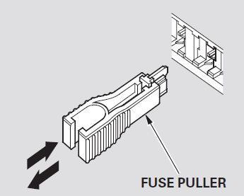 |
| Fuse Puller |
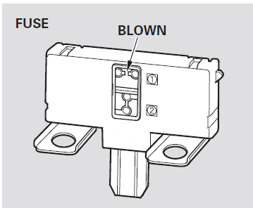
5. Look for a blown wire inside the fuse. If it is blown, replace it with one of the spare fuses of
the same rating or lower.
 |
| Blown Fuse |
Notice - Replacing a f use with one that has a higher rating greatly increases the chances of damaging the electrical system. If you do not have a replacement fuse with the proper rating f or the circuit, install one with a lower rating.
6. If you cannot drive the vehicle without fixing the problem, and you do not have a spare fuse, take a fuse of the same rating or a lower rating from one of the other circuits. Make sure you can dowithout that circuit temporarily (such as the accessory power socket or radio).
If you replace the blown fuse with a spare fuse that has a lower rating, it might blow out again. This does not indicate anything wrong. Replace the fuse with one of the correct rating as soon as you can.
Spare Fuses
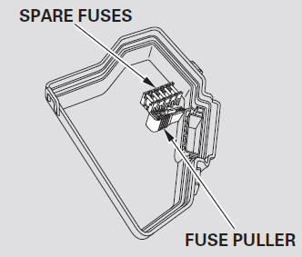 |
| Spare Fuses, Fuse Puller Location |
All models except DX
If the driver’s power window fuse is removed, the AUTO function of the driver’s window will be disabled. You should reset the AUTO feature.
If the radio fuse is removed, the audio system will disable itself. The next time you turn on the radio you will see ‘‘ENTER CODE’’ in the frequency display. Use the preset buttons to enter the digit code .
When the audio system is disabled, the clock setting in the audio system will be canceled. You will need to reset the clock.
INTERIOR FUSE BOX
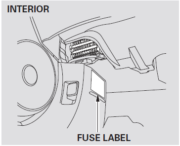
The interior fuse box is underneath the steering column.
| Circuits Protected | Amp. | No. |
| Power Window | 7.5 | 1 |
| Fuel Pump | 15 | 2 |
| Alternator | 10 | 3 |
| ABS/VSA | 7.5 | 4 |
| Heated Seat* | 15 | 5 |
| Not Used (Front Fog Light* 20A - 2011 Models) | - | 6 |
| Not Used (TFMS* 7.5A - 2008 - 2011 Models) | - | 7 |
| Not Used | - | 8 |
| ODS | 7.5 | 9 |
| METER | 7.5 | 10 |
| SRS (Supplemental restraint system) | 10 | 11 |
| Right Headlight High Beam |
10 | 12 |
| Left Headlight High Beam |
10 | 13 |
| Small Light (Interior) | 7.5 | 14 |
| Small Light (Exterior) | 7.5 | 15 |
| Right Headlight Low beam | 10 | 16 |
| Left Headlight Low beam | 10 | 17 |
| Headlight High beam Main | 20 | 18 |
| Small Lights (Main) | 15 | 19 |
| Not Used | - | 20 |
| Headlight Low Beam Main | 20 | 21 |
| (HAC)* | 7.5 | 22 |
| STS* | 7.5 | 23 |
| Moonroof * |
20 | 24 |
| Door Lock | 20 | 25 |
| Driver’s Power Window | 20 | 26 |
| Not Used | - | 27 |
| Rear ACC Socket* | -15 | 28 |
| ACC (Adaptive Cruise Control) | 15 | 29 |
| Passenger’s Power Window | 20 | 30 |
| Not Used | - | 31 |
| Right Rear Power Window | 20 | 32 |
| Left Rear Power Window | 20 | 33 |
| Not Used | - | 34 |
| Accessory Radio | 7.5 | 35 |
| HAC* | 10 | 36 |
| Daytime Running Light | 7.5 | 37 |
| Front Wiper | 30 | 38 |
* : If equipped
UNDER - HOOD FUSE BOX
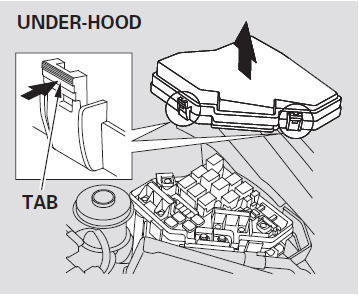
The under-hood fuse box is on the driver’s side, next to the brake fluid reservoir. To open it, push the tabs as shown.
| Circuits Protected | AMP. | No. |
| Main Fuse | 100 | 1 |
| EPS * | 70 | |
| Option Main | 80 | 2 |
| Ignition Switch Main | 50 | |
| ABS/VSA Motor | 30 | 3 |
| ABS/VSA F/S | 30 | |
| 40 * | ||
| Headlight Main | 50 | 4 |
| Power Window Main | 40 | |
| Not Used | - | 5 |
| Sub Fan Motor | 20 | 6 |
| Main Fan Motor (M/T) | 20 | 7 |
| Main Fan Motor (A/T) | 30 | |
| Rear Defogger | 30 | 8 |
| Blower | 40 | 9 |
| Hazard | 10 | 10 |
| FI Sub | 15 | 11 |
| Stop and Horn | 15 | 12 |
| Not Used | - | 13 |
| Not Used | - | 14 |
| IGPS Oil Level | 7.5 | 15 |
| Not Used | - | 16 |
| Audio Amp** | 15 | 17 |
| IG Coil | 15 | 18 |
| FI Main | 15 | 19 |
| MG Clutch | 7.5 | 20 |
| DBW (Drive by wire) | 15 | 21 |
| Interior Light | 7.5 | 22 |
| Back Up | 10 | 23 |
* : U.S. Si model
** If equipped





No comments:
Post a Comment