 |
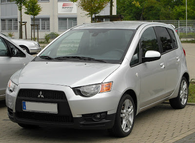
| 2010 Mitubushi colt |
Fuse block location
To prevent damage to the electrical system due to shortcircuiting or overloading, each individual circuit is provided with a fuse.
There is a fuse block in the passenger compartment.
 |
| Passenger compartment fuse location (LHD) |
 |
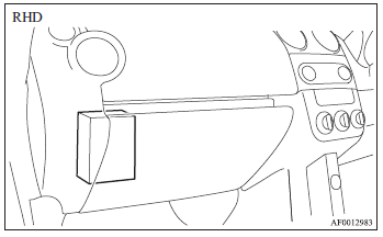
| Passenger compartment fuse location (RHD) |
The location of the fuse block in the passenger compartment depends whether the vehicle is LHD (Left Hand Drive) or RHD (Right Hand Drive). In a LHD vehicle, it is located behind the cover in front of the driver’s seat. In a RHD vehicle, it is located at the back of the glove box (as shown in the illustration).
Fuse load capacity
The fuse capacities and the names of the electrical systems protected by the fuses are shown on the back of the cover in a LHD vehicle and behind the cover at the back of the glove box in a RHD vehicle.
NOTE - The vehicle is not equipped with spare fuses. Please purchase replacement fuses as necessary.
Passenger compartment fuse location table
NOTE - When replacing a fuse, be sure to use a fuse of the same capacity.
 |
| Passenger compartment fuse Panel Diagram(LHD) |
 |
| Passenger compartment fuse location (RHD) |
No. ... Electrical system ...Capacity
1 Ignition switch 40 A
2 Electric window system 40 A
3 Radiator fan 40 A
4 Automated manual transmission 40 A
5 Demister 30 A
6 Heated seat 30 A
7 — — —
8 Heater 40 A
9 Radio 10 A
10 Room lamp 10 A
11 Heated door mirror 7.5 A
12 Electronic control module 7.5 A
13 Windscreen wiper 20 A
14 Tail lamp (right) 7.5 A
15 Tail lamp (left) 7.5 A
16 Engine 20 A
17 Fuel pump 15 A
18 Horn 10 A
19 Headlamp (left) high-beam10 A
20 Headlamp(right) high-beam 10 A
21 — — —
22 — — —
23 Outside rear-view mirrors 7.5 A
24 Rear fog lamp 7.5 A
25 Accessory socket 15 A
26 Rear window wiper 15 A
27 — — —
28 — — —
29 — — —
30 — — —
31 Hazard warning flasher 10 A
32 — — —
33 Door locks 15 A
34 Front fog lamps 15 A
35 Headlamp low beam (left) 10 A
36 Headlamp low beam (right) 10 A
37 Reversing lamp 7.5 A
38 Engine control 7.5 A
39 Ignition coil 10 A
40 Gauge 7.5 A
41 Relay 7.5 A
42 STOP Stop lamps 15 A
43 Air conditioning 7.5 A
44 — — —
- Some fuses may not be installed on your vehicle,depending on the vehicle model or specifications.
- The table above shows the main equipment corresponding to each fuse.
Identification of fuse
Capacity Colour
7.5 A Brown
10 A Red
15 A Blue
20 A Yellow
30 A Green
40 A Orange (fuse type)/Green (fusible link type)
Fuse replacement
1. Before replacing a fuse, always turn off the electrical circuit concerned and place the ignition switch in the “LOCK” position.2. Remove the fuse puller from the cover.
3. Referring to the fuse load capacity table, check the fuse pertaining to the problem.
 |
A- Fuse is OK , B- Blown fuse
|
NOTE
l If any system does not function but the fuse corresponding to that system is normal, there may be a fault in the system elsewhere. We recommend you to have your vehicle checked.
4. Insert a new fuse of the same capacity by using the fuse puller and insert the fuse at the
same place in the fuse block.
 |
| Fuse Puller |
CAUTION
l If the newly inserted fuse blows again after a short time, we recommend you to have the electrical system checked to find the cause and rectify it.
l Never use a fuse with a capacity larger than that specified or any substitute, such as wire, foil, etc.; doing so will cause the circuit wiring to heat up and could cause a fire.

No comments:
Post a Comment