 |
| 2017 Mitsubishi Outlander |
Fuse block location
To prevent damage to the electrical system due to short-circuiting or overloading, each individual circuit is provided with a fuse.
There are fuse blocks in the passenger compartment and in the engine compartment.
Passenger compartment (LHD vehicles)
The fuse blocks in the passenger compartment are located behind the fuse lid in front of the driver’s seat at the position shown in the illustration.
Pull the fuse lid to remove it.
 |
| Main fuse block , Sub fuse block |
A- Main fuse block
B- Sub fuse block
B- Sub fuse block
Passenger compartment (RHD - Right Hand Drive vehicles)
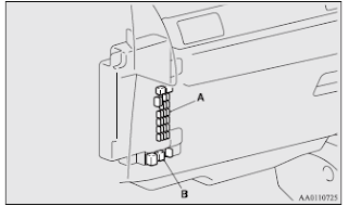
The fuse boxes in the passenger compartment are located behind the glove box at the position shown in the illustration.
A- Main fuse block
B- Sub fuse block
B- Sub fuse block
Main fuse block
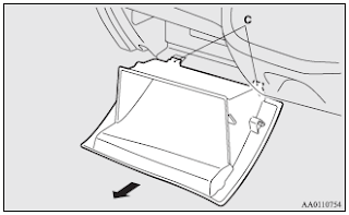
1. Open the glove box.
2. Uncouple the rod (A) on the right side of the glove box.
2. Uncouple the rod (A) on the right side of the glove box.
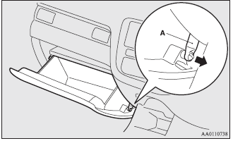 |
| Main fuse block |
3. While pressing the side of the glove box, unhook the left and right hooks (B) and lower the glove box.
4. Remove the glove box fastener (C), and then remove the glove box.
Sub fuse block
When changing the fuse of the sub fuse block, perform it with the hole of the bottom cover.
 |
| Sub fuse block |
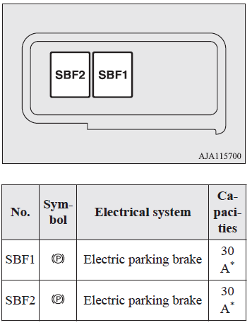
Engine compartment Fuse Block
In the engine compartment, the fuse blocks are located as shown in the illustration. While pressing the tab (D), pull up the cover.
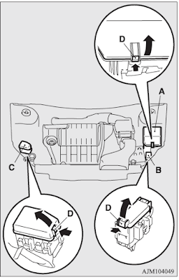 |
| Engine compartment Fuse Box Location |
A- Main fuse block
B- Sub fuse block (Type 1)
C- Sub fuse block (Type 2)
B- Sub fuse block (Type 1)
C- Sub fuse block (Type 2)
Fuse load capacity
The fuse capacity and the names of electrical systems protected by the fuses are indicated
on the inside of the fuse lid (LHD vehicles), the back side of the glove box (RHD vehicles)
and inside of the fuse block cover (inside of the engine compartment).
NOTE - Spare Fuses
- Spare fuses are provided on the cover of main fuse block in the engine compartment.Always use a fuse of the same capacity for replacement.
Passenger compartment fuse Panel Diagram
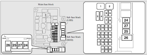 |
| Passenger compartment Fuse Panel Diagram |
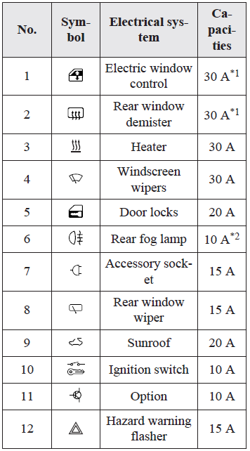
Passenger compartment Fuse Table
No. ..... Electrical system .... Capacities
1 Electric (Power) window control 30 A*1
2 Rear window demister (Defogger) 30 A*1
3 Heater 30 A
4 Windscreen wipers 30 A
5 Door locks 20 A
6 Rear fog lamp 10 A*2
7 Accessory socket (12 V power outlet) 15 A
8 Rear window wiper 15 A
9 Sunroof 20 A
10 Ignition switch 10 A
11 Option 10 A
12 Hazard warning flasher 15 A
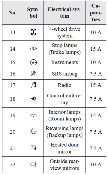
13 4-wheel drive system 10 A
14 Stop lamps (Brake lamps) 15 A
15 Instruments 10 A
16 SRS airbag 7.5 A
17 Radio 15 A
18 Control unit relay 7.5 A
19 Interior lamps (Room lamps) 15 A
20 Reversing lamps (Backup lamps) 7.5 A
21 Heated door mirror 7.5 A
22 Outside rearview mirrors 10 A
14 Stop lamps (Brake lamps) 15 A
15 Instruments 10 A
16 SRS airbag 7.5 A
17 Radio 15 A
18 Control unit relay 7.5 A
19 Interior lamps (Room lamps) 15 A
20 Reversing lamps (Backup lamps) 7.5 A
21 Heated door mirror 7.5 A
22 Outside rearview mirrors 10 A
23 Cigarette lighter/ Accessory socket 15 A
24 Charge 7.5 A , Heated steering wheel 15 A
25 Power seat (Driver seat) 30 A*1
26 Heated seat 30 A
27 (2016 - 2020 Models - Power seat (Passenger seat) 30 A*1 )
24 Charge 7.5 A , Heated steering wheel 15 A
25 Power seat (Driver seat) 30 A*1
26 Heated seat 30 A
27 (2016 - 2020 Models - Power seat (Passenger seat) 30 A*1 )
Comments
*1: Fusible link
*2: Even if your vehicle is equipped with the rear fog lamp, the fuse of the rear fog lamp may not be installed on your vehicle.
*2: Even if your vehicle is equipped with the rear fog lamp, the fuse of the rear fog lamp may not be installed on your vehicle.
- Some fuses may not be installed on your vehicle, depending on the vehicle model or specifications.
- The table above shows the main equipment corresponding to each fuse.
- The table above shows the main equipment corresponding to each fuse.
 |
| Passenger compartment fuse location table |
Comments
*1: Fusible link
*2: Even if your vehicle is equipped with the rear fog lamp, the fuse of the rear fog lamp may not be installed on your vehicle.
*2: Even if your vehicle is equipped with the rear fog lamp, the fuse of the rear fog lamp may not be installed on your vehicle.
 |
| Passenger compartment fuse location table |
 |
| Passenger compartment fuse location table |
Engine compartment Fuse Box Diagram
 |
| Engine compartment fuse Panel Diagram |
Engine compartment Fuse Table
No. .... Electrical system .... Capacities
SBF1 Air conditioning condenser fan motor 30 A* , VLC 40 A*
SBF2 Starter 30A*
SBF3 Air conditioning condenser fan motor 30 A*
SBF4 Radiator fan motor 40A*
SBF5 Anti-lock brake system (ABS) 40A*
SBF6 Electric parking brake 50A*
SBF7 Anti-lock brake system (ABS) 30A*
BF1 Electric tailgate 30 A
BF2 Audio system amp 30 A
BF3 IOD IOD 30 A
BF4 Diesel 30 A
F1 Automatic transmission 20 A
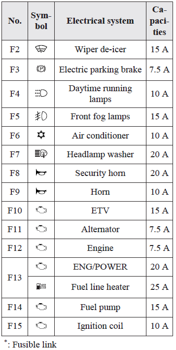
F2 Wiper de-icer 15 A
F3 Electric parking brake 7.5 A
F4 Daytime running lamps 10 A
F5 Front fog lamps 15 A
F6 Air conditioner 10 A
F7 Headlamp washer 20 A
F8 Security horn 20 A
F9 Horn 10 A
F10 ETV 15 A
F11 Alternator 7.5 A
F12 Engine 7.5 A
F13 ENG/POWER 20 A , Fuel line heater 25 A
F14 Fuel pump 15 A
F15 Ignition coil 10 A
F16 ENG/POWER 10 A
F17 Headlamp high-beam (left) 10 A
F18 Headlamp high-beam (right) 10 A
F19 Headlamp low beam (left) LED 20 A
F20 Headlamp low beam (right) LED 20 A
F21 Headlamp low beam (left) Halogen 10 A
F22 Headlamp low beam (right) Halogen 10 A
F23 Battery current sensor 7.5 A
#1 — Spare fuse 10 A
#2 — Spare fuse 15 A
#3 — Spare fuse 20 A
Comment
*: Fusible link
- Some fuses may not be installed on your vehicle, depending on the vehicle model or specifications.
- The table above shows the main equipment corresponding to each fuse.
- The table above shows the main equipment corresponding to each fuse.
 |
Engine compartment Fuse Table |
 |
| Engine compartment fuse table |
 |
| Engine compartment fuse table |
- Some fuses may not be installed on your vehicle, depending on the vehicle model or specifications.
- The table above shows the main equipment corresponding to each fuse.
- The table above shows the main equipment corresponding to each fuse.
Sub fuse block (Type 1)
*: Fusible link
- Some fuses may not be installed on your vehicle, depending on the vehicle model or specifications.
- The table above shows the main equipment corresponding to each fuse.
- Some fuses may not be installed on your vehicle, depending on the vehicle model or specifications.
- The table above shows the main equipment corresponding to each fuse.
Sub fuse block (Type 2)
 |
Sub fuse block (Type 2)
|
*: Fusible link
- Some fuses may not be installed on your vehicle, depending on the vehicle model or specifications.
- The table above shows the main equipment corresponding to each fuse.
The fuse box does not contain spare 7.5 A, 25 A or 30 A fuses. If one of these fuses burns out, substitute with the following fuse.
7.5 A: 10 A spare fuse
25 A: 20 A spare fuse
30 A: 30 A audio system amp fuse
When using a substitute fuse, replace with a fuse of the correct capacity as soon as possible.
Identification of fuse
Capacity Colour
7.5 A Brown
10 A Red
15 A Blue
20 A Yellow
25 A Natural (White)
30 A Green (fuse type) / Pink (fusible link type)
40 A Green (fusible link type)
50 A Red (fusible link type)
Fuse replacement
1. Before replacing a fuse, always turn off the electrical circuit concerned and place the ignition switch in the “LOCK” position or put the operation mode in OFF.2. Remove the fuse puller (A) from the inside of the fuse block cover in the engine
compartment.
 |
| Fuse Puller Location |
3. Referring to the fuse load capacity table, check the fuse pertaining to the problem.
 |
| Blown Fuse , Normal Fuse |
B- Fuse is OK
C- Blown fuse
C- Blown fuse
NOTE
- If any system does not function but the fuse corresponding to that system is normal, there may be a fault in the system elsewhere. We recommend you to have your vehicle checked.
- If any system does not function but the fuse corresponding to that system is normal, there may be a fault in the system elsewhere. We recommend you to have your vehicle checked.
4. Insert a new fuse of the same capacity by using the fuse puller into the same place the fuse block.
 |
| Fuse Puller |
CAUTION
- If the newly inserted fuse blows again after a short time, we recommend you to have the electrical system checked to find the cause and rectify it.
- Never use a fuse with a larger capacity than specified or a substitute (such as a cable or foil). Doing so could cause the circuit wires to overheat and create a fire.


No comments:
Post a Comment