Softail and Dyna models have several circuit breakers to protect the motorcycle wiring. They are: main, lighting, accessory, instruments and ignition. Each of these breakers is self-resetting and automatically returns steady power to the circuit when an electrical fault that causes it to trip is found and corrected. If the electrical fault is not found and corrected, the breaker cycles on and off causing the motorcycle to operate erratically and eventually the battery will lose its charge.
All other models have a main circuit breaker. For electrical problems, it is best to see your Harley-Davidson dealer who has necessary parts and equipment to perform electrical services.
Fuse Block Location
FLT and XL models have fuses located under left side cover, FX models have fuses located under the seat.
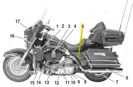 |
| Ultra Electra Glide Classic FLHTCU-I - Left Side View - 5 - Fuse Block Location |
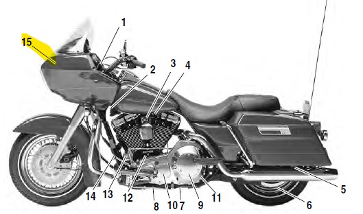 |
| Road Glide FLTR-I - Left Side View - Fuse Block Location - 15 |
FLT MODELS FUSE REPLACEMENT
If it is necessary to replace the radio or the CB/Intercom fuses, carefully follow the procedures below or see your Harley-Davidson dealer for service. Do not skip any steps or damage to the sound system and/or other motorcycle systems may result.
PRELIMINARY INSTRUCTIONS
1. Place the Ignition/Light Key Switch in the OFF position.
2. Raise lid of left side saddle bag. Grasp bail wire inside saddlebag and rotate each stud a full 1/4 turn in a counter-clockwise direction. Remove bail head studs with flat washers. Remove saddlebag.
3. Gently pull side cover from frame downtubes (no tools required). Radio fuses are located in the fuse block, CB/ Intercom fuses are in the fuse box.
RADIO FUSE REPLACEMENT - FLHTC/FLHTC-I/FLHTC-U/FLHTCU-I
1. See Preliminary Instructions on this page.
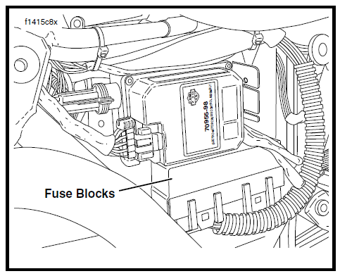
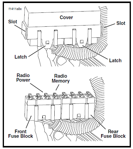
2. Pull fuse blocks from tabs on mounting panel. Tabs on panel fit into slots on each side of fuse block cover. To remove cover, raise latches slightly to disengage tabs on fuse blocks
3. Locate the two radio fuses in the front fuse block. The 10 amp fuse allows power to the radio through activation of an internal relay. The 15 amp fuse provides direct and continuous power to the radio memory and clock and when the internal relay is activated, feeds the main circuits of the radio as well.
 |
| Left Side Cover Removed - FLHTCU |
 |
| Fuse Blocks |
4. Using the puller tool in the fuse block cover, remove the fuse and inspect the element. Replace the fuse if the element is burned or broken. Automotive type ATO fuses are used.
NOTE
Two spare fuses (one each) can be found in the fuse block cover.
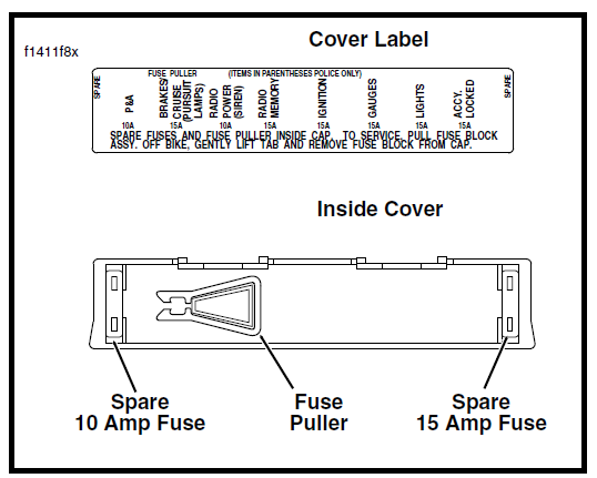 |
| Fuse Block Cover |
CAUTION
Always use replacement fuses that are of the correct type and value. Use of incorrect fuses can result in damage to electrical systems.
5. Slide cover over fuse blocks until latches fully engage tabs on blocks. Slide fuse blocks into position on mounting panel. Tabs on panel fit into slots on each side of fuse block cover.
6. See Final Instructions.
6. See Final Instructions.
FINAL INSTRUCTIONS
1. Align barbed studs in side cover with grommets in frame downtubes and push firmly into place (no tools required).
2. Position left side saddlebag on vehicle. Place flat washers on bail head studs. Insert stud through holes in saddlebag and front mounting bracket. When groove on stud engages wire form of spring plate on inboard side of bracket, turn stud clockwise a full 1/4 turn until it snaps in place. Install rear bail head stud in the same manner.
XL MODELS FUSE REPLACEMENT
1. Place the Ignition in the OFF position.
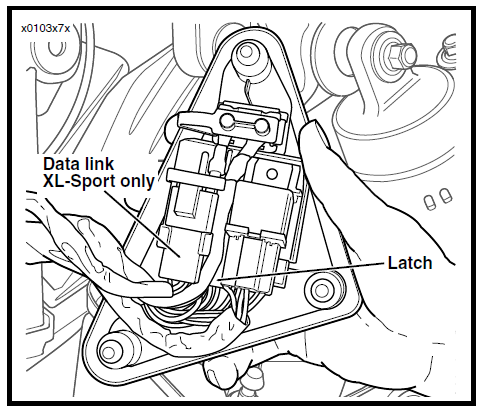
2. See Figure 52 and 53. Gently pull left side cover from frame (no tools required). Lift latch on fuse block holder to remove fuse block.
2. See Figure 52 and 53. Gently pull left side cover from frame (no tools required). Lift latch on fuse block holder to remove fuse block.
NOTE
Two spare fuses and a puller tool can be found in the fuse block cover.
Two spare fuses and a puller tool can be found in the fuse block cover.
3. Using the puller tool, remove the fuse and inspect the element. Replace the fuse if the element is burned or broken. Automotive type ATO fuses are used.
CAUTION
Always use replacement fuses that are of the correct type and value. Use of incorrect fuses can result in damage to electrical systems.
4. Slide fuse block into holder until latche fully engages tab on holder.
5. Align barbed studs in side cover with grommets in frame and push firmly into place (no tools required).
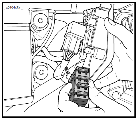 |
| XL Fuse Block |

No comments:
Post a Comment