 |
| 2022 Chevrolet Bolt EV |
Fuses and Circuit Breakers
The wiring circuits in the vehicle are protected from short circuits by a combination of fuses and circuit breakers.
This greatly reduces the chance of damage caused by electrical problems.
Danger
Fuses and circuit breakers are marked with their ampere rating. Do not exceed the specified amperage rating when replacing fuses and circuit breakers. Use of an oversized fuse or circuit breaker can result in a vehicle fire. You and others could be seriously injured or killed.
Fuses and circuit breakers are marked with their ampere rating. Do not exceed the specified amperage rating when replacing fuses and circuit breakers. Use of an oversized fuse or circuit breaker can result in a vehicle fire. You and others could be seriously injured or killed.
Warning
Installation or use of fuses that do not meet GM’s original fuse specifications is dangerous. The fuses could fail, and result in a fire. You or others could be injured or killed, and the vehicle could be damaged.
To check a fuse, look at the silver-colored band inside the fuse. If the band is broken or melted, replace the fuse. Be sure to replace a bad fuse with a new one of the identical size and rating.
Fuses of the same amperage can be temporarily borrowed from another fuse location, if a fuse goes out. Replace the fuse as soon as possible.
Underhood Compartment Fuse Block
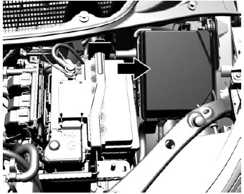
To open the fuse block cover, press the clips at the side and back and pull the cover up.
Caution
Spilling liquid on any electrical component on the vehicle may damage it. Always keep the covers on any electrical component.
 |
| Engine Compartment Fuse Panel Diagram |
A fuse puller is in the underhood compartment fuse block.
The vehicle may not be equipped with all of the fuses, relays, and features shown.
The vehicle may not be equipped with all of the fuses, relays, and features shown.
Fuses ... Usage
1 –
2 Power Window Rear
3 Cargo Lamp
4 Rechargeable Energy Storage System 1
5 Power Seat Driver
7 –
8 –
9 –
10 –
11 Horn
12 –
13 Front Wiper Motor Driver
15 Front Wiper Motor Co-driver
16 Electronic Brake Control Module Supply Electronics
17 Rear Wiper
18 Liftgate
19 Seat Module Front
20 Washer
22 Linear Power Module
23 Electronic Brake Control Module Supply Motor
24 Power Seat Lumbar
26 Transmission Range Control Module
27 Aeroshutter
28 Auxiliary Oil Pump
29 Electric Brake Boost Motor Source
30 Front Power Windows
31 In-panel Bussed Electrical Center
32 Rear Window Defogger
33 Heated Exterior Rearview Mirror
34 Pedestrian Friendly Alert Function
35 –
36 –
37 Current Sensor
38 –/Humidity Sensor
39 –
40 Electric Brake Boost (ECU)
41 Power Line Communication Module
42 Infant Only Supression
43 Window Switch
44 Rechargeable Energy Storage System
45 Vehicle Integration Control Module
46 Shifter Interface Board
47 Humidity Sensor
48 Shifter Interface Board
49 Interior Rearview Mirror
50 –
51 Electric Brake Boost
52 –
54 A/C Control Module
55 Rechargeable Energy Storage System Coolant Pump
56 –
57 Power Electronics Coolant Pump
58 Engine Control Module
59 –
60 HVAC (Heating, ventilation, and air conditioning) Electric Heater
61 On-board Charging Module
62 Transmission Range Control Module 1
63 Electric Cooling Fan
64 Engine Control Module
65 Auxiliary Heater Pump
66 Powertrain
67 Drive Unit Controller
70 A/C Control Module
71 –
72 Transmission Range Control Module
73 Single Power Inverter Module
74 –
Relays Table
Relays ... Usage
6 Pedestrian Friendly Alert Function
14 Liftgate
21 –
25 Powertrain
53 Run/Crank
68 Rear Window Defogger
69 Second Run/Crank
6 Pedestrian Friendly Alert Function
14 Liftgate
21 –
25 Powertrain
53 Run/Crank
68 Rear Window Defogger
69 Second Run/Crank
Instrument Panel Fuse Box
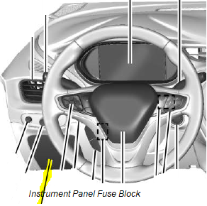
The instrument panel fuse block is on the left side of the instrument panel. To access the fuses, open the fuse panel door by pulling out.
To reinstall the door, insert the top tab first, then push the door back into its original location.
To reinstall the door, insert the top tab first, then push the door back into its original location.
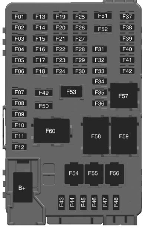
Fuses ... Usage
F01 Video Processing Module
F02 Indicator Light Solar Sensor (2023 Model - TCP – Telematics Control Platform (OnStar) )
F03 Side Blind Zone Alert
F04 Passive Entry, Passive Start
F05 CGM – Central Gateway Module
F06 Body Control Module 4
F07 Body Control Module 3
F08 Body Control Module 2
F09 Body control module 1
F10 Police SSV
F11 Amplifier
F12 Body Control Module 8
F13 Data Link Connector
F14 Parking Assist
F15 Headlamp LH
F16 Single Power Inverter Module 1
F17 Body Control Module 6
F18 Body Control Module 5
F19 –
F20 –
F21 –
F22 –
F23 USB
F24 Wireless Charging Module
F25 Reflected LED Alert Display
F26 Heated Steering Wheel
F27 CGM – Central Gateway Module 2
F28 Instrument Cluster 2
F29 –
F30 –
F31 TCP – Telemetics Control Platform (OnStar)
F32 –
F33 Heating, Ventilation, and Air Conditioning Module
F34 Heating, Ventilation and Air Conditioning Display/ Integrated Center Stack
F35 Instrument Cluster 1
F36 Center Stack Module
F37 –
F38 –
F39 –
F40 –
F41 –
F42 –
F43 Body Control Module 7
F44 Sensing and Diagnostic Module
F45 Front Camera Module
F46 Vehicle Integration ControlModule
F47 Single Power Inverter Module 2
F48 Headlamp RH
F49 Auxiliary Jack
F50 Steering Wheel Controls
F51 –
F52 –
F53 Auxiliary Power Outlet
F54 –
F55 Logistic
F56 Police SSV
Relays ... Usage
F57 Police SSV
F58 Logistics Relay
F59 –
F60 Accessory/Retained Accessory Power Relay


No comments:
Post a Comment