Fuses and Relays
Fuses are simple circuit breakers which protect the vehicle electrical equipment by preventing the electrical circuits from being overloaded. A blown fuse indicates that the item of electrical equipment it protects stops working.
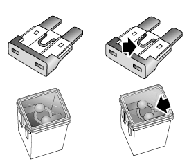
Check a suspect fuse by removing it from the fuse box and looking for a break in the wire inside the fuse.
It is recommended to have spare fuses in the vehicle, which can be obtained from a local MG Authorised Repairer.
Comparison Before and After the Fuse is Blown
 |
| Good Fuse - Blown Fuse |
IMPORTANT
• NEVER attempt to repair a blown fuse. ALWAYS replace a fuse with one of the same rating.
• If a replaced fuse fails immediately, please contact an MG Authorised Repairer as soon as possible.
Fuse Box
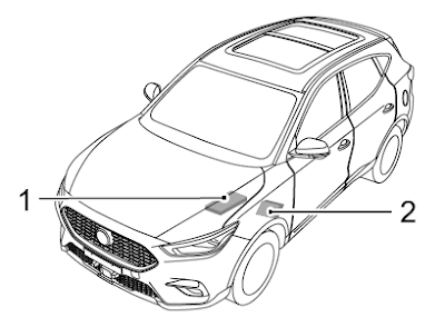
1 Front Compartment Fuse Box(at the left side of the Front Bay).
2 Passenger Compartment Fuse Box(below the glove box at the front passenger side).
2 Passenger Compartment Fuse Box(below the glove box at the front passenger side).
Passenger Compartment Fuse Box
Check or Replace a Fuse
1 Switch off the vehicle power system and all electrical equipment, disconnect the battery negative cable.
2 Remove the closing panel below the glove box to gain access to the fuse box.
3 Press the fuse extraction tool onto the fuse head and pull to remove the fuse. A blown fuse can be recognised by a break in the wire.
4 Replace the blown fuse with a same rating.
Fuse Specification Chart
NO. ... Specs ... Function
F1 15A Front Washer Relay, Rear Washer Relay
F2 10A Diagnostic Socket
F3 5A PRND Display
F4 10A Front Left Seat Heating Relay
F5 10A Airbag ECU (SDM)
F6 10A Keyless Start/Stop Switch, Gateway
F7 30A Driver Seat Adjust Switch
F8 15A Super Lock Relay
F9–F11 - -
F12 5A Left Rear Driving Assistance Radar
F13–F14 - -
F15 15A Front Power Socket (Cigarette Lighter)
F16 5A Front Courtesy Lamp, Outside Mirror and Master Light Height Adjust Switch, Top USB, Left Headlamp Assembly, Right Headlamp Assembly
F17 5A Rear USB
F18 5A EPB Switch
F19 5A Outside Mirror and Master Light Height Adjust Switch, Rain Light Sensor
F20 10A Front Right Seat Heating Relay
F21 10A 360° View Module, Passenger Compartment Fuse F12
F22 10A Exterior Mirrors Heating Element
F23 25A Rear Windscreen Heating Element
F24 20A Front Central Display, Front Infotainment Control Module
F25 10A Electronic Temperature Controller
F26 5A Instrument Pack
F27 10A Transmission Control Module-AT
F28 5A Information Faceplate
F29 30A Sunroof
F30 5A DAB Module
F31 5A Tyre Pressure Monitoring System
F32 10A Electronic Steering Column Lock
F33 30A Sunroof
F34–F41 - -
F42 25A Stability Control Module(Valve)-MT
F42 40A Stability Control Module(Valve)-AT
F43 30A Passenger Window lift Switch, Rear Left Window Lift Switch
F44 30A Driver Door Switch Pack, Driver Window Lifter, Rear Right Window Lift Switch
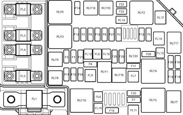
Front Compartment Fuse Box
Check or Replace a Fuse
1 Switch off the vehicle power system and all electrical equipment, disconnect the battery negative cable.
2 Press the locating clips to remove the fuse box lid.
3 Press the fuse extraction tool onto the fuse head and pull to remove the fuse. A blown fuse can be recognized by a break in the wire.
4 Replace the fuse with a same rating.
Fuse Specification Chart
NO. ... Specs ... Function
FL1 150A Alternator
FL2 80A Electric Power Steering Module
FL3 40A Cooling Fan Relay Pack
FL4 80A Windscreen/Mirror Heating Relay, Passenger Compartment Fuse F18, F19, F20, F21, F42, F43, F44
FL5 80A KLR Relay, Passenger Compartment Fuse F1, F2, F3, F4, F5, F6, F7, F8, F24, F25,
F26, F27, F28, F29, F30, F31, F32, F33
FL6 - -
FL7 40A Electronic Temperature Controller, Blower
FL8 20A Body Control Module
FL9 40A Stability Control Module(Pump)
FL10 - -
FL11 - -
FL12 - -
FL13 30A Starter Relay
FL14 - -
FL15 - -
FL16 30A DC/DC Convertor
FL17 - -
F1 10A Right Headlamp Assembly
FL8 20A Body Control Module
FL9 40A Stability Control Module(Pump)
FL10 - -
FL11 - -
FL12 - -
FL13 30A Starter Relay
FL14 - -
FL15 - -
FL16 30A DC/DC Convertor
FL17 - -
F1 10A Right Headlamp Assembly
F2 15A Downstream Lambda Sensor, Upstream Lambda Sensor, Positive Temperature Coefficient(1.5L), Intake Variable Camshaft Timing(1.0T), Exhaust Variable Camshaft timing(1.0T), Oil Control Valve(1.0T), Canister Purge Valve(1.0T)
F3 10A Left Headlamp Assembly
F4 10A Compressor Relay
F5 5A Engine Control Module
F6 10A Fuel Injector(1.5L)
F7 30A Front Wiper Enable Relay, Front Wiper High/Low Speed Relay
F8 5A Cooling Fan Relay Pack, Brake Pedal Switch, Fuel Pump Relay, AC Pressure Switch, Neutral Switch(1.5L)
F9 20A Fuel Pump Relay
F10 10A Right Headlamp Assembly
F11 10A Left Headlamp Assembly
F12 30A Ignition Coil, Engine Control Module
F13 15A Horn Relay
F14 - -
F15 10A Intake Variable Camshaft Timing(1.5L), Exhaust Variable Camshaft Timing(1.5L), Canister Purge Valve(1.5L), Electronic Thermostat(1.0T), Electronic Water Pump(1.0T), Dump
Valve(1.0T), Waste Gate Control Valve(1.0T), Clutch Master Cylinder Sensor(1.0T)
F16 15A Rear Wiper Relay
F17 10A Fog Lamp Relay
F18 5A Airbag ECU (SDM)
F19 5A Instrument Pack, Front Detect Radar, Front View Control Module, Shifter Mechanism, Reverse Lamp Switch, DC/DC Convertor, Airbag Display Module F20 5A Engine Control Module
F21 25A Body Control Module
F22 - -
F23 - -
F24 - -
F25 30A Body Control Module
F26 - -
F27 15A Body Control Module
F28 - -
F29 - -
F30 5A Engine Control Module


No comments:
Post a Comment