 |
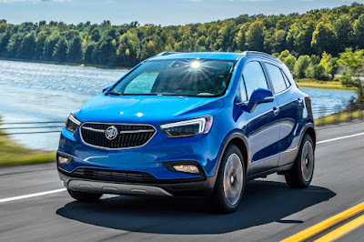
| 2017 Buick encore |
Fuses and Circuit Breakers
The wiring circuits in the vehicle are protected from short circuits by a combination of fuses and circuit breakers. This greatly reduces the chance of damage caused by electrical problems.
To check a fuse, look at the silver-colored band inside the fuse. If the band is broken or melted, replace the fuse. Be sure to replace a bad fuse with a new one of the identical size and rating.
Fuses of the same amperage can be temporarily borrowed from another fuse location, if a fuse goes out. Replace the fuse as soon as possible.
Engine Compartment Fuse Block
 |
| Engine Compartment Fuse Block Location |
To remove the fuse block cover, squeeze the clip and lift it up.
Caution
Spilling liquid on any electrical component on the vehicle may damage it. Always keep the
covers on any electrical component.
Spilling liquid on any electrical component on the vehicle may damage it. Always keep the
covers on any electrical component.
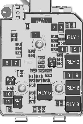 |
| Engine Compartment Fuse Panel Diagram |
The vehicle may not be equipped with all of the fuses, relays, and features shown.
Mini Fuses .. Usage
1 Sunroof
2 Exterior rearview mirror switch/Driver side power window/ Rain sensor/ Universal garage door opener
3 Canister vent solenoid
4 –
5 Electronic brake control module valve
6 Intelligent battery sensor
7 Electric steering column lock
8 Transmission control module/FICM
9 Automatic occupancy sensing module
10 Headlamp leveling switch/Headlamp leveling motor/Rear vision camera/ Interior rearview mirror
11 Rear wiper
12 Rear window defogger
13 Power lumbar switch
14 Exterior rearview mirror heater
15 Fuel system control module battery
16 Heated seat module/ Memory module
17 TIM DC DC converter/Fuel system control module RC/ Compass module
18 Engine control module RC/ Transmission control module RC/ FICM RC
19 Fuel pump
20 –
21 Fan relay (auxiliary BEC)
22 –
23 Ignition coil/ Injector coil
24 Washer pump
25 Automatic headlamp leveling
26 EMS Var 1
27 –/Auxiliary heater pump
28 –/Engine control module powertrain/ Ignition 3
29 Engine control module powertrain/ Ignition 1/Ignition 2
30 EMS Var 2
31 Left high-beam headlamp
32 Right high-beam headlamp
33 Engine control module battery
34 Horn
35 A/C (Air Conditioner) clutch
36 Front fog lamps
J-Case Fuses .. Usage
1 Electronic brake control module pump
2 Front wiper
3 Linear power module blower
4 IEC RC
5 –
7 –/Starter solenoid
8 Cooling fan low – mid
9 Cooling fan – high
10 EVP ( Electric vacuum pump)
11 Starter solenoid/ Starter pinion
U-Micro Relays ... Usage
2 Fuel pump
4 –/Auxiliary heater pump
HC-Micro Relays ... Usage
7 Starter/Starter pinion
10 Starter solenoid
Mini Relays ... Usage
1 Run/Crank
3 Cooling fan – mid
5 Powertrain relay
8 Cooling fan – low
HC-Mini Relays .. Usage
6 Cooling fan – high
6 Cooling fan – high
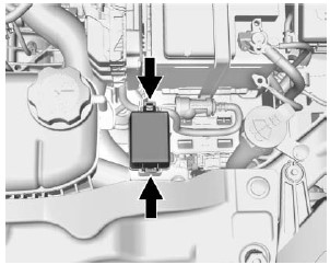
Auxiliary Fuse Block
To remove the fuse block cover, squeeze the clips and lift it up.
Caution
Spilling liquid on any electrical component on the vehicle may damage it. Always keep the
covers on any electrical component.
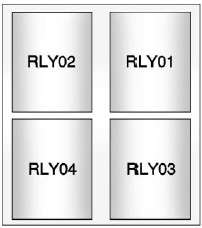
Relays ... Usage
01 Electric vacuum pump
02 Cooling fan control 1
03 Cooling fan control 2
04 N/A
Instrument Panel Fuse Block
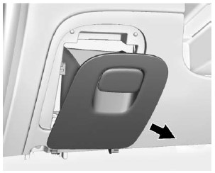 |
| Instrument Panel Fuse Block Location |
The instrument panel fuse block is on the underside of the driver side
instrument panel. To access the fuses, remove the storage compartment.
To remove the storage compartment, open the compartment and pull it out.
The vehicle may not be equipped with all of the fuses, relays, and features shown.
Fuses .. Usage
F1 Body control module 1
F2 Body control module 2
F3 Body control module 3
F4 Body control module 4
F5 Body control module 5
F6 Body control module 6
F7 Body control module 7
F8 Body control module 8
F9 Discrete logic ignition switch
F10 Sensing diagnostic module battery
F11 Data link connector
F12 HVAC module/ICS
F13 Liftgate relay
F14 Central gate module
F15 Lane departure warning/GENTEX
F16 Adaptive forward lighting module
F17 Electrical steering column lock
F18 Parking assist module/Side blind zone alert
F19 Body control module/Regulated voltage control
F20 Clock spring
F21 A/C/Accessory power outlet/PRNDL
F22 Auxiliary power outlet/DC center
F23 HVAC module/ICS
F24 –
F25 OnStar module/ Eraglonass
F26 Heated steering wheel
F27 Instrument panel cluster/Auxiliary heater/Auxiliary virtual image display
F28 Trailer feed 2
F29 Faceplate
F30 DC/DC 400W
F31 Instrument panel cluster module battery
F32 Silver box audio module/Navigation
F33 Trailer feed 1
F34 Passive entry/ Passive start
Midi Fuses .. Usage
M01 Positive temperature coefficient (PTC)
S/B Fuses .. Usage
S/B01 Passenger power seat
S/B02 –
S/B03 Front power windows
S/B04 Rear power windows
S/B05 Logistic mode relay
S/B06 Driver power seat
S/B07 –
S/B08 Trailer interface module
S/B08 Trailer interface module
Circuit Breaker ... Usage
CB1 –
Relays .. Usage
RLY01 Accessory/Retained accessory power
RLY02 Liftgate
RLY03 –
RLY04 –
RLY05 Logistic mode
Rear Compartment Fuse Block (2016 - 2017 Models)
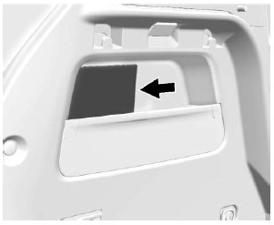 |
| Rear Compartment Fuse Block Location |
The rear compartment fuse block is behind a cover on the driver side of the rear compartment. To access the fuses, remove the cover.
The vehicle may not be equipped with all of the fuses, relays, and features shown.
 |
| Rear Compartment Fuse Panel Diagram |
Fuses .. Usage
F1 –
F2 –
F3 Amplifier audio
F4 –
F5 Rear drive control module
F6 Left cornering lamp
F7 Right cornering lamp
F8 –
F9 –
F10 –
F11 –
F12 –
F13 –
F14 –
F15 –
F16 –
F17 –
F18 –
F2 –
F3 Amplifier audio
F4 –
F5 Rear drive control module
F6 Left cornering lamp
F7 Right cornering lamp
F8 –
F9 –
F10 –
F11 –
F12 –
F13 –
F14 –
F15 –
F16 –
F17 –
F18 –
S/B Fuses .. Usage
S/B01 –
S/B02 –
S/B03 –
S/B04 DC/AC inverter module
S/B05 –
S/B06 –
S/B07 DC-DC transformer 400W
S/B08 DC-DC transformer 400W
S/B09 –
Relays .. Usage
RLY01 Right cornering lamp
RLY02 Left cornering lamp
Rear Compartment Fuse Block (2018 - 2020 Models)
 |
| Rear Compartment Fuse Block Location |
The rear compartment fuse block is behind a cover on the driver side of the rear compartment. To access the fuses, remove the cover.
The vehicle
may not be equipped with all of the fuses, relays, and features shown.
Fuses ... Usage
F1 Amplifier audio
F2 Rear drive control module
F3 –
F4 –
F5 –
F6 –
F7 –
F8 –
F9 –
F10 –
F11 –
F12 –
F13 –
F14 –
F15 –
F16 –
F17 –
F1 Amplifier audio
F2 Rear drive control module
F3 –
F4 –
F5 –
F6 –
F7 –
F8 –
F9 –
F10 –
F11 –
F12 –
F13 –
F14 –
F15 –
F16 –
F17 –
S/B Fuses .. Usage
S/B01 DC-DC transformer 400W
S/B02 DC-DC transformer 400W
S/B03 DC/AC inverter module
S/B04 –
S/B05 –
Relays ... Usage
RLY01 –
RLY02 –
RLY03 –
RLY04 –
RLY05 –
Circuit Breakers ... Usage
CB1 –



No comments:
Post a Comment