Fuses and Relays
CAUTION
Never replace a fuse with one having a higher rating or with material other than a fuse because serious damage or a fire could result.
The fuses are designed to melt during an overload to prevent damage to the wiring harness and electrical equipment. The fuses are located in two fuse boxes.
One is located under the instrument panel behind the fuse box cover on the driver’s seat side. To remove the cover, pull it out.
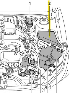
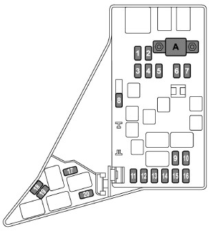
The other one (main fuse box) is housed in the engine compartment. Also, the spare fuses are stored in the fuse box cover.
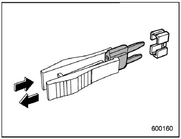
The fuse puller is stored in the main fuse box in the engine compartment.
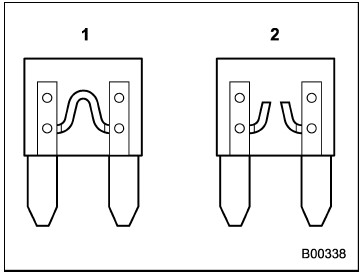
1) Good
2) Blown
2) Blown
If any lights, accessories or other electrical controls do not operate, inspect the corresponding fuse. If a fuse has blown, replace it.
1. Turn the ignition switch to the “LOCK”/ “OFF” position and turn off all electrical accessories.
2. Remove the cover.
3. Determine which fuse may be blown.
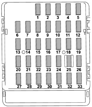
Fuse Panel Diagram Location - Fuse rating and using circuit are described on each behind the fuse box cover.
4. Pull out the fuse with the fuse puller.
5. Inspect the fuse. If it has blown, replace it with a spare fuse of the same rating.
6. If the same fuse blows again, this indicates that its system has a problem. Contact your SUBARU dealer for repairs.
5. Inspect the fuse. If it has blown, replace it with a spare fuse of the same rating.
6. If the same fuse blows again, this indicates that its system has a problem. Contact your SUBARU dealer for repairs.
Passenger Compartment Fuse Panel
# .. Fuse rating .. Circuit
1 20A . Trailer hitch connector
2 15A —
3 15A . Door locking
4 10A . Front wiper deicer relay
5 10A . Combination meter, Clock
6 7.5A . Remote control rear view mirrors . Seat heater relay
7 15A . Combination meter . Integrated unit
8 10A . Stop light
9 15A . Front wiper deicer
10 7.5A . Power supply (battery)
11 7.5A . Turn signal unit
12 15A . Transmission control unit . Engine control unit . Integrated unit
13 20A . Accessory power outlet (center console) . AC110V (If installed)
14 15A . Parking light . Tail light . Rear combination light
15 10A . Luggage light . Clock
16 7.5A . Illumination
17 15A . Seat heaters
18 10A . Backup light
19 7.5A . Power window relay . Radiator main fan relay
20 10A . Accessory power outlet (instrument panel)
21 10A . Starter relay
22 7.5A . Air conditioner . Rear window defogger relay coil
23 Empty
24 10A . Audio unit . Clock
25 15A . SRS (supplemental restraint system) airbag system
26 Empty
27 15A . Blower fan
28 15A . Blower fan
29 15A . Fog light
30 Empty
31 7.5A . Auto air conditioner unit . Integrated unit
32 7.5A . Clutch switch . Steering lock control unit
33 7.5A . Vehicle Dynamics Control unit
Engine Compartment Fuse Panel
# ... Fuse rating .. Circuit
1 30A . ABS unit . Vehicle Dynamics Control unit
2 25A . Main fan (cooling fan)
3 25A . Sub fan (cooling fan)
4 Empty
5 Empty
6 30A . Headlight (low beam)
7 15A . Headlight (high beam)
8 20A . Back-up
9 15A . Horn
10 25A . Rear window defogger . Mirror heater
11 15A . Fuel pump
12 20A . Continuously variable transmission control unit
13 7.5A . Engine control unit
14 15A . Turn and hazard warning flasher
15 15A . Tail and illumination relay
16 7.5A . Alternator
17 Empty
18 10A . Telematics (2013 Model - Empty)
19 15A . Headlight (low beam – right hand)
20 15A . Headlight (low beam – left hand)




No comments:
Post a Comment